Hexadecimal LED Display
08 Feb 2022 ∞
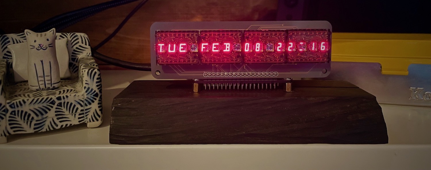
A while ago saw a link to some old LED hexadecimal displays, DL2416s, little four character modules that accept ASCII and have an LED matrix for the display. I was captivated by them and purchased a handful from eBay with the idea that I'd use them as a thermostat as part of my home automation.
Long story short, I designed a very flawed circuit board that I never quite got working correctly, and abandoned the project. Recently I decided to pick it back up and realized that not once had anyone needed to control the heating via a physical device, so I scrapped it and figured I'd just build a single generic 16-character display.
The Hardware
One goal I had was to minimize the visible PCB, which was tricky because of the through-hole sockets for the display modules. Eventually I decided on a two PCB design: one display module and one logic board for the microcontroller. This would allow the two PCBs to be mounted at 90º and give some flexibility for which microcontroller to use.
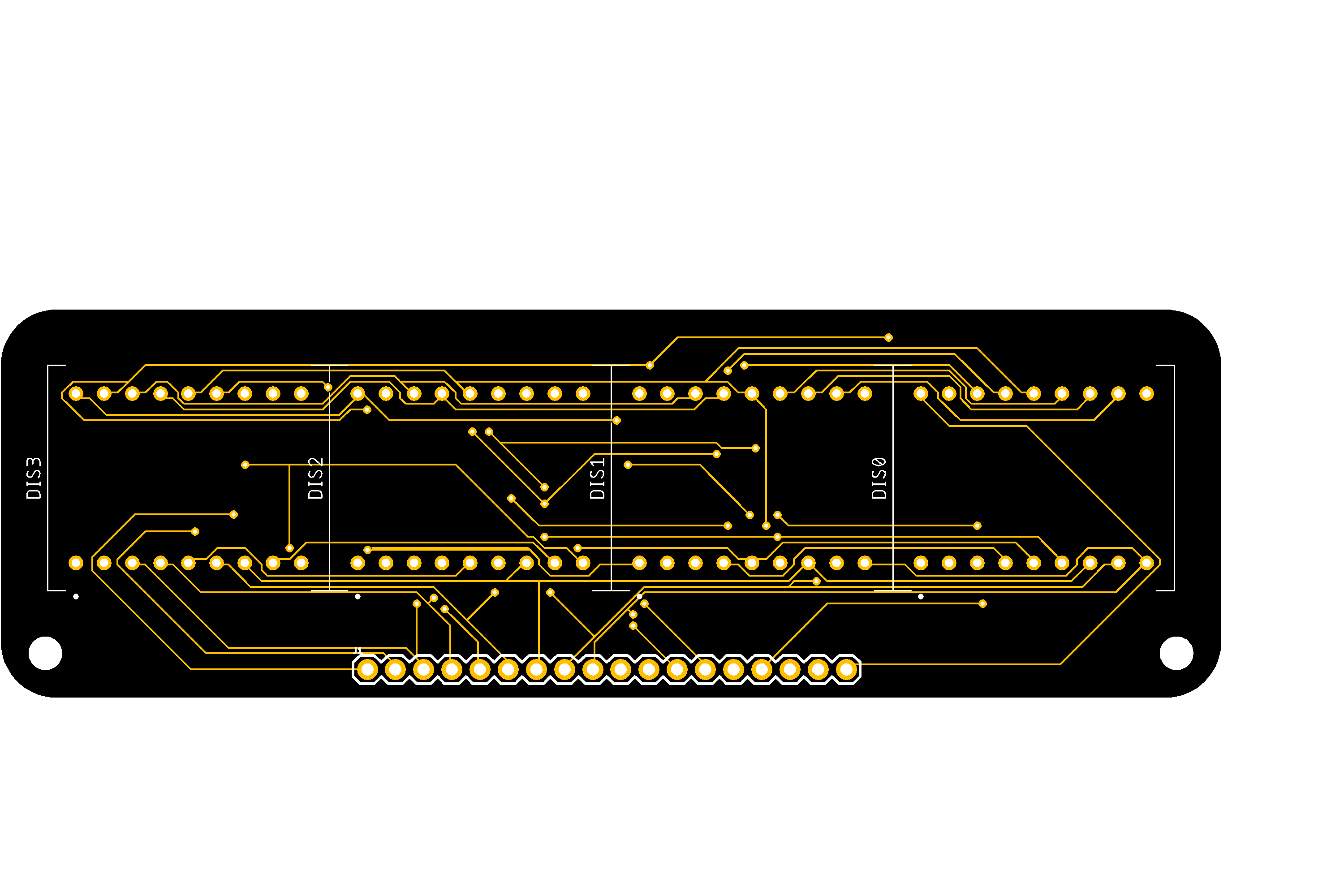
While prototyping everything on a breadboard I'd never used more than two displays simply due to the wiring complexity. Each display requires 18 pins, all of which are connected together. While I would have liked to have installed all four displays, at the end of the day it wouldn't have mattered because I'd still be routing everything in CAD anyway with no way of knowing I'd transferred all of the wires correctly.
Once I got the PCBs back and soldered all of the components into place I was relieved to find I had wired everything technically correctly, save one issue that I probably would have found had I prototyped all four displays and a Raspberry Pi Pico instead of an Arduino.
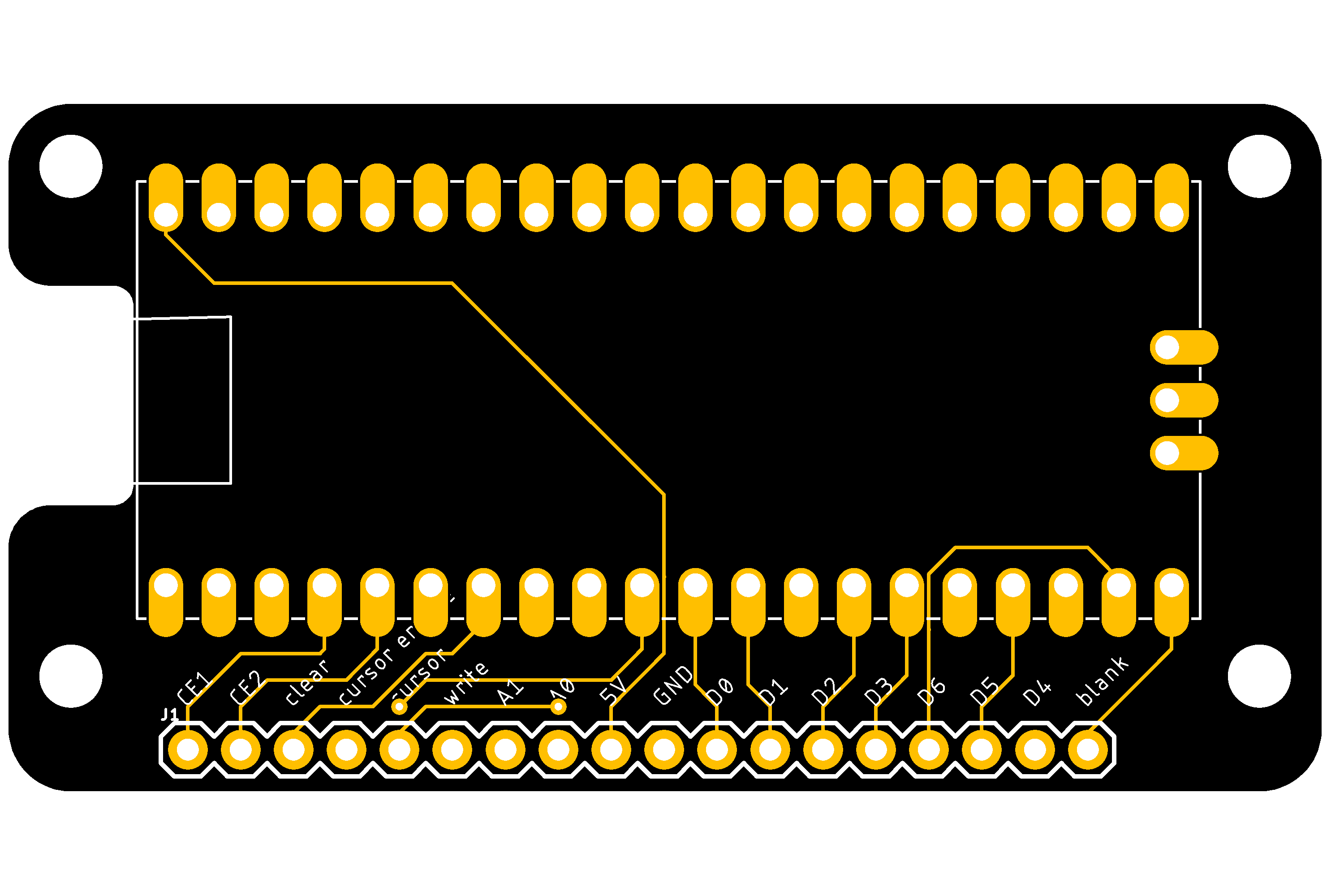
Each digit is addressed with four pins: two chip selects and two digit selects. Something that took me far too long to realize is that when these pins are ordered correctly they make a single 16-bit number, one for each character. When connecting the pins to the Pico I simply matched the pin order of the displays. Had I thought about it I would have realized that placing the pins on adjacent GPIOs (like I did with the data pins) would have meant I could sent the digit enable in a single step.
The Software
Controlling the display is relatively simple:
- Select the digit
- Pull
writelow - Write the ASCII character
- Pull
writehigh
Similarly a cursor can be shown by setting the bit while the cursor write pin is low, and all cursors can be shown or not with the cursor enable pin. You can also blank the entire display.
With the hardware and basic logic working I next question was what to do with it. The first thing I did while testing reading characters over USB was build a simple terminal based on ASCII control characters. It also serves double duty by allowing a program to interact with the display.
This was also the foundation of the first "real" application: a serial clock. I updated a program I'd written for the 8-character breadboard prototype to make use of the full display and control characters. This worked, but came with the limitation that the Pico couldn't display the time on its own.
The Pico luckily has its own real-time clock (RTC), however setting that clock is a different matter. The simplest way is to just write a program that sends each date and time component bit-by-bit and reassembling it on the other end. On the Pico each component has a fixed length, so counting up the bits isn't too hard.
Letting the Pico handle the date has the advantage of not needing to keep the serial connection open and lets a launch agent reset the clock when the Pico is reconnected.
The Finishing Touches
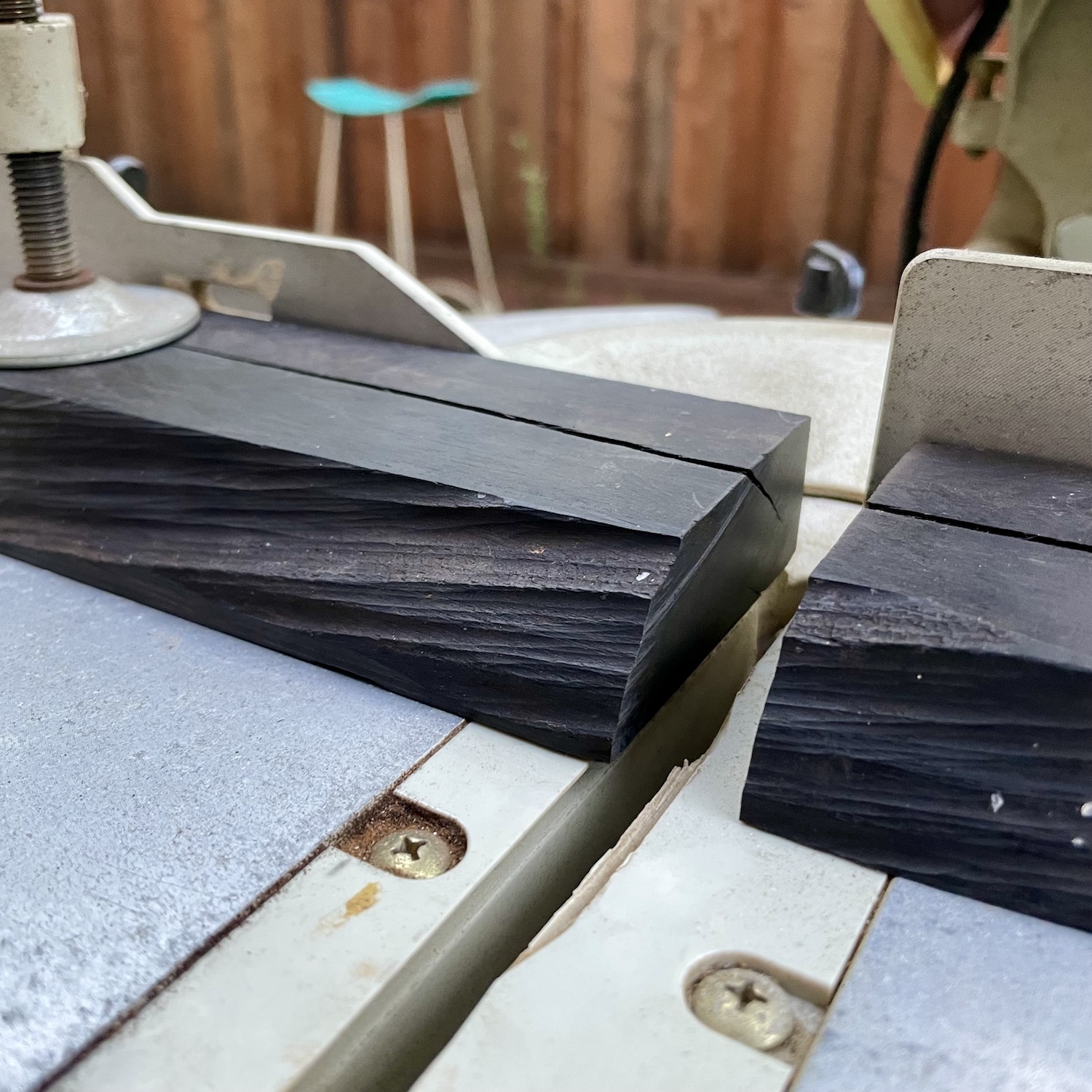
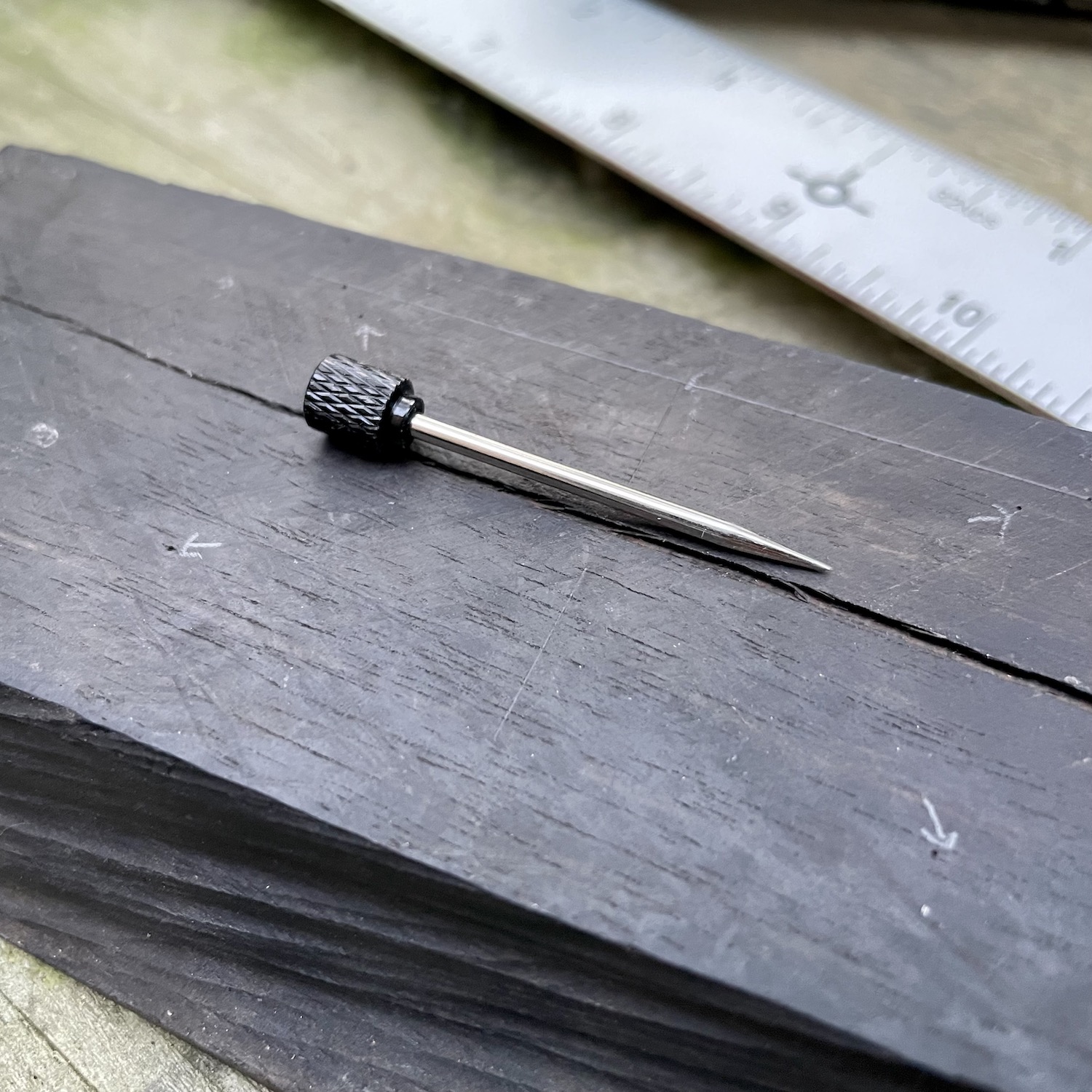
The final thing I needed to do was find a suitable stand. I figured heading to my local fancy lumber yard and sorting through the scrap bin would be the way to go, and indeed it was. I found a rough hewn piece of ebony wood that really fit the dark PCB and red LEDs.
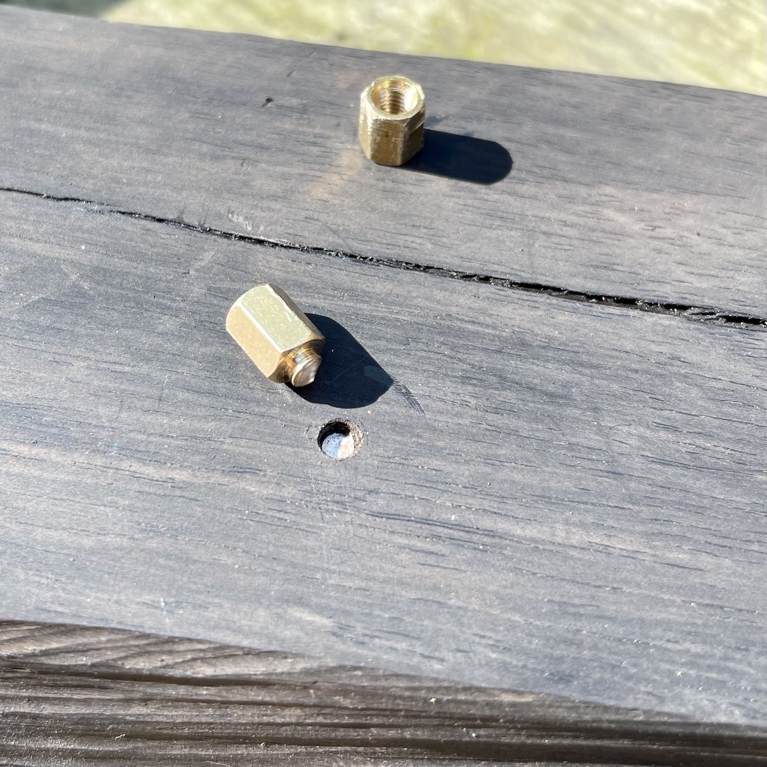
I proceeded to measure and mark out the length and holes for the standoffs. Unfortunately I decided to do that as the sun was setting and messed up the locations of two of the holes. I filled them and re-drilled, being much more careful, only to break off not one, but two standoffs!
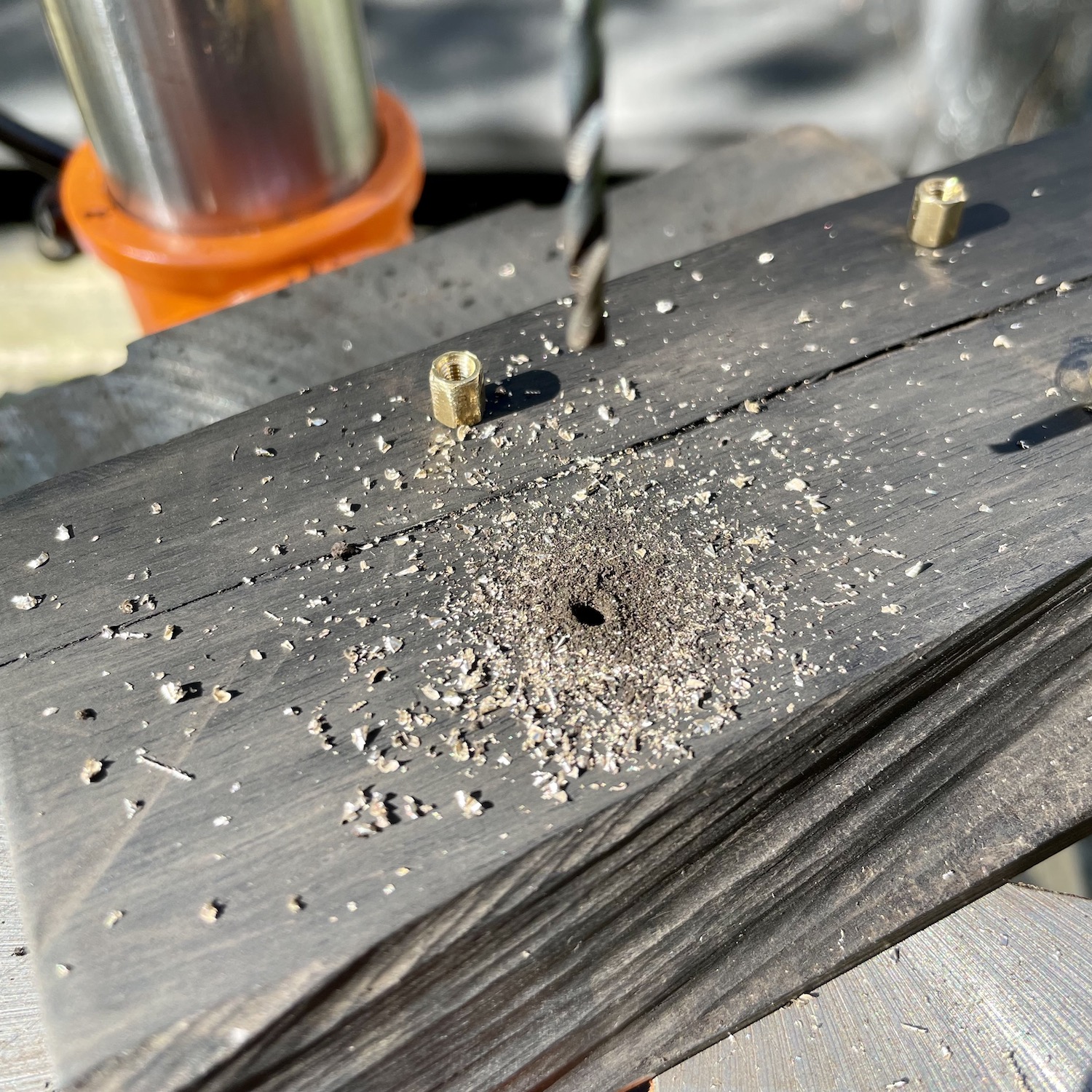
After a couple of tries I got them all in the correct positions and everything assembled. I'm considering adding a bandpass filter in front of the displays, which according to the datasheet will help increase the contrast of the LEDs against background, and a nicer right-angle USB cable.