Recently I released an update for Take Stock that added a number of features I've wanted to have since the first release. There are also a bunch of smaller improvements, and even some bug fixes.
The biggest change was moving the film rolls from the top tab bar to the sidebar. The tabs were fully custom, and while I spent a lot of time trying to get them just right, they were always a little finicky. As a result I decided to move them to the sidebar, which comes with a lot of benefits. You've always been able to drop both images and folders into Take Stock, now the two are more clearly defined as Folders and Collections. These are now in separate sections in the sidebar, making it more clear which is which.
With the new position in the sidebar comes a big quality of life improvement. Previously when writing metadata Take Stock would simply show a spinner1 with no indication it was making forward progress. With this update the progress is tracked in a lovely determinate progress bar, showing exactly what's going on.
Equipment management has also been improved with new keyboard shortcuts for navigating between sidebar tabs and adding cameras, lenses, and film stocks. Additionally when deleting one there is now a confirmation step2.
In the bug-fixes department the text fields for entering exposure information behave correctly, allowing values like 5.6 to be entered correctly. In some cases metadata would fail to be updated when writing for a second time, so this has been fixed.
This update was a long time coming, and I think really improves Take Stock. Give it a download and let me know what you think.
Which could sometimes get stuck, which is also fixed.↩
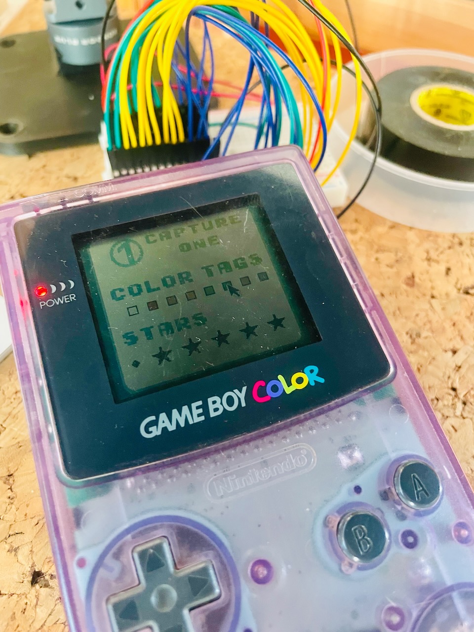
A couple years ago I built a GameBoy app and hardware accessory for controlling Capture One. It was a great project, and I learned about GameBoy programming for the first time, did a deeper dive on embedded Swift, and explored wireless communication on a lower level. The result worked surprisingly well, allowing someone to navigate images and set color tags & star ratings.
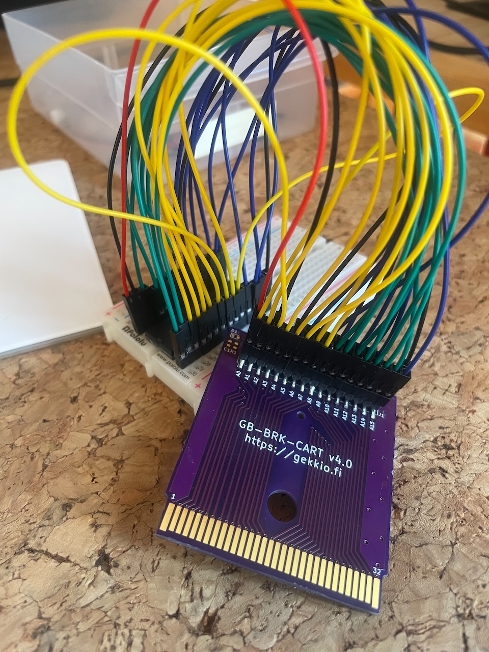
The project wasn't the most user-friendly, requiring something like an Analogue Pocket to load the ROM and the hardware used the link cable, which meant a wire to manage. I knew I wanted to take it a level further: a custom all-in-one GameBoy cartridge that housed all of the components.
I figured it ought to be possible, after all modern microcontrollers are fast, why not just wire up the edge connector pins to GPIO and call it a day? It didn't take long to realize that, perhaps, wasn't the best course of action. It would make more sense to let the microcontroller handle coordination and use an EEPROM for the GameBoy side of things.
After thinking about some of the basics I came up with a set of requirements for my cart:
Entirely self-contained
Wireless communication to a computer
GameBoy to RP2040 communication via RAM
Flashable EEPROM from the RP2040
The EEPROM
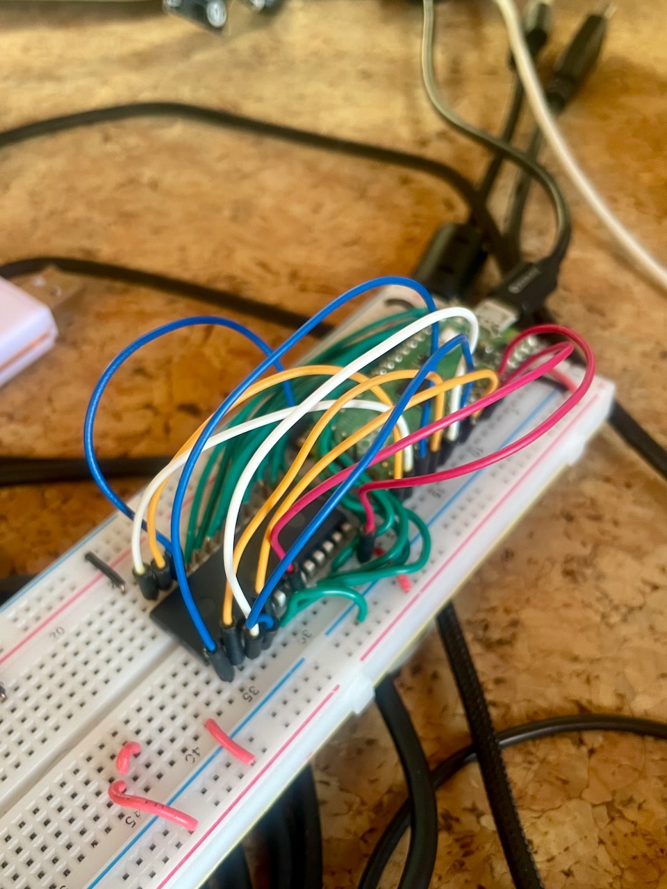
I didn't have a dedicated EEPROM flasher, so I started by building one with a Pico as that was one of the design goals anyway. The EEPROM is fairly simple: you give it an address, ask to read or write, and then it either puts some data on the bus or you do. The timing for reading or writing are generous, it could even be done by hand. There are 16 address lines, eight data lines, plus control logic, all which need to be connected between the EEPROM, the Pico, and the cart header, all just a matter of connecting a bunch of jumper wires.
There was a little bit of logic needed around reading and writing. A normal game is read-only, and the EEPROM is hard wired that way. In order for the Pico to write to the EEPROM we can't do that, the pin needs to be controllable. Unfortunately the write enable pin isn't only used when writing to the EEPROM, it's used when writing anything to the bus. As a result if we simply connected the pin we'd end up rewriting our game code with garbage.
To solve this I pulled some logic gates out of the components drawer and got to work. While the GameBoy has 16 address lines, the EEPROM itself only has 15. In fact, that high bit is only low when the GameBoy wants to access the ROM, all other addresses on the bus leave it high, so run everything through an OR gate and we should be all set1.
Getting the EEPROM to flash successfully took a fair amount of work, lots of wiring issues and bugs in my code. Then finally it worked. Watching my own code boot on my childhood GameBoy was nothing short of amazing, and still hasn't gotten old2.
The Bus
When I built the prototype I used the link port for communication, as that was the only way for the GameBoy to send data to the outside world. The link port communicates via SPI, shifting one bit at a time, which was fine, but could be better for our use case. The GameBoy supports external RAM, usually used for save states, but why not have the RP2040 act as write-only memory?
Modifying the code was easy, instead of sending data via the link port all it takes is writing data to specific addresses. I chose the first few bytes of RAM:
This way simply writing a value to either property causes the GameBoy to write the data to the bus, including pulling the write enable low. To test this I loaded the ROM up in a GameBoy emulator and debugger called bgb. Watching the memory inspector confirmed that our bytes were indeed being written to RAM as expected when I pressed a button.
As for wiring, everything was already done! The Pico was already on the bus, so it just had to wait for its stop3. This is where I ran into some issues. My initial approach was to set an interrupt on the write enable pin and then check if an address was either of our pointers and then pull the data. This did not work, there was just too much happening on the bus. Even running the interrupt on the second core by the time the interrupt was serviced the GameBoy was onto the next thing.
I ended up having to put the second core in a fast loop just checking the write enable and address lines, and even then had to have the game write the same data to RAM multiple times to ensure the Pico would catch one of them. There are some other projects which suggest this could be handled by PIO, though adding address decoding with discrete logic to filter out anything other than writes to the external RAM is another option.
Wireless
The final step in all of this was adding wireless communication so the GameBoy wouldn't need to be tethered to a computer. I'd been prototyping with a normal Pico, so I swapped it out for a Pico-W and got to work. The client app ran a basic socket server to which the Pico would connect and send the full command (both the key and value). Getting the Pico connected to Wi-Fi with stored credentials turned out to be the hardest part.
In order to get everything set up the cart is connected via USB to the companion app which sends over the network info, from there the Pico stores it in flash for use later. There are still plenty of improvements to be made so the whole process is easier, mostly notably mDNS.
The Result
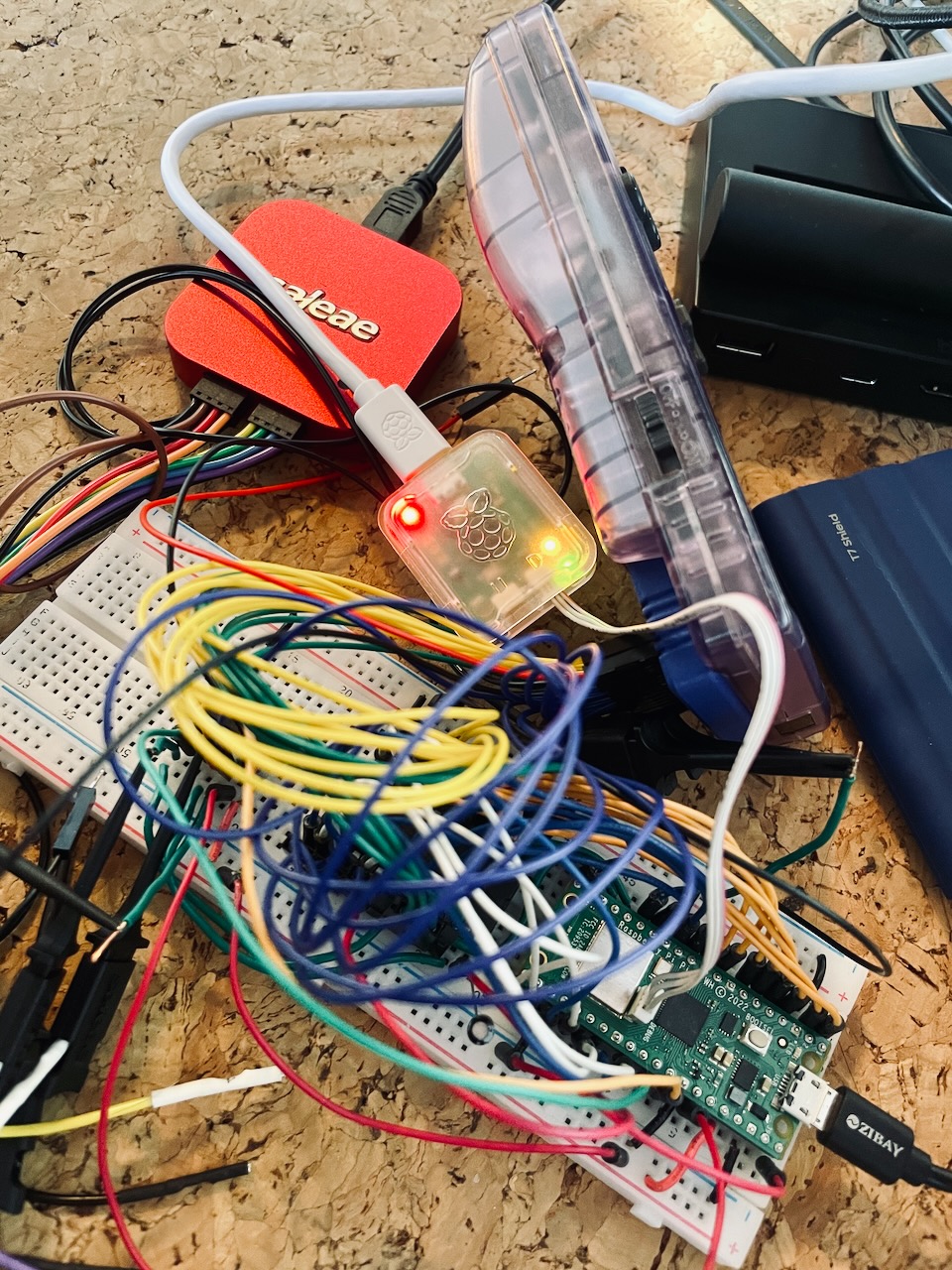
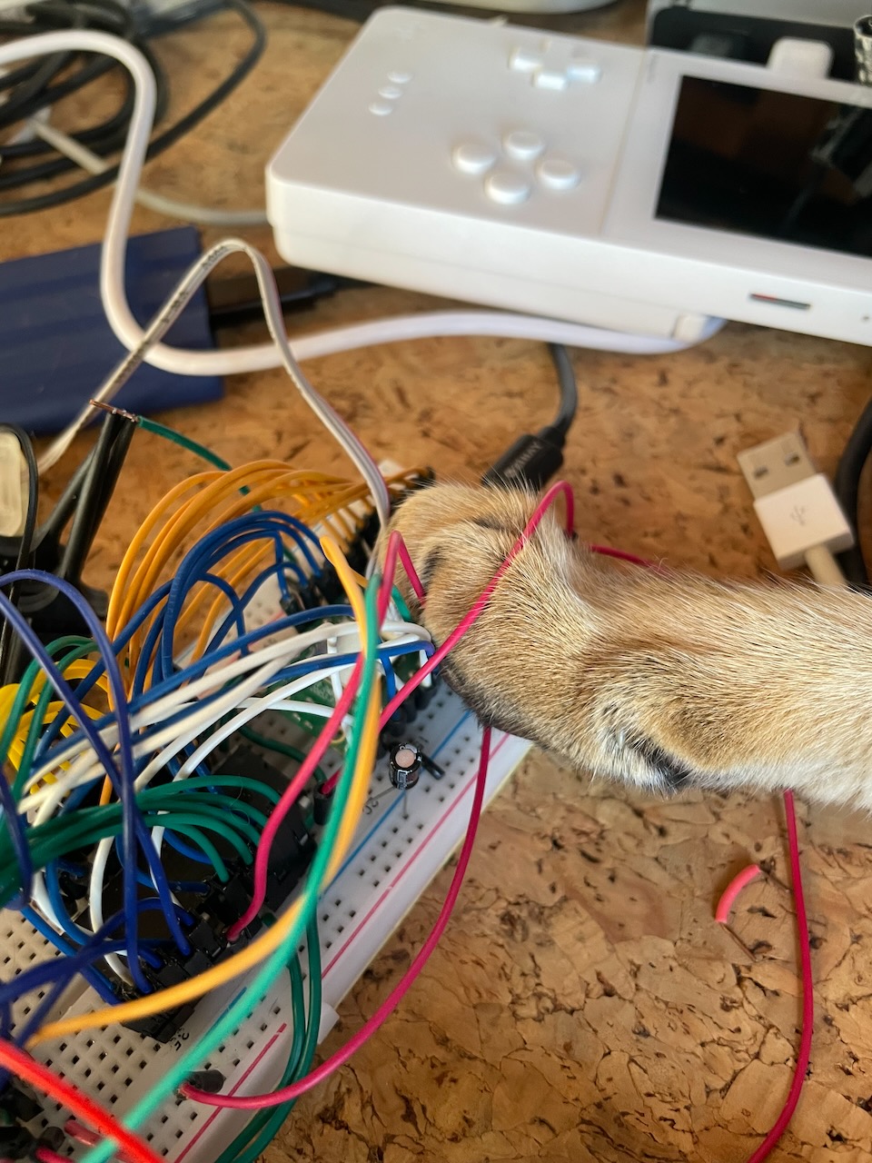
It took weeks of tinkering with the software and hardware, and so much rewiring, but it did all eventually work. The Pico can write the binary to the EEPROM, which the GameBoy launches, and finally sends commands via RAM back to the Pico which forwards them wirelessly to the client software that controls Capture One.
However that's just a tangle of wires on a breadboard, the next step is putting it all together on a PCB. That's going to be a separate post in the future, with its own tales of design and debugging, of which there are many.
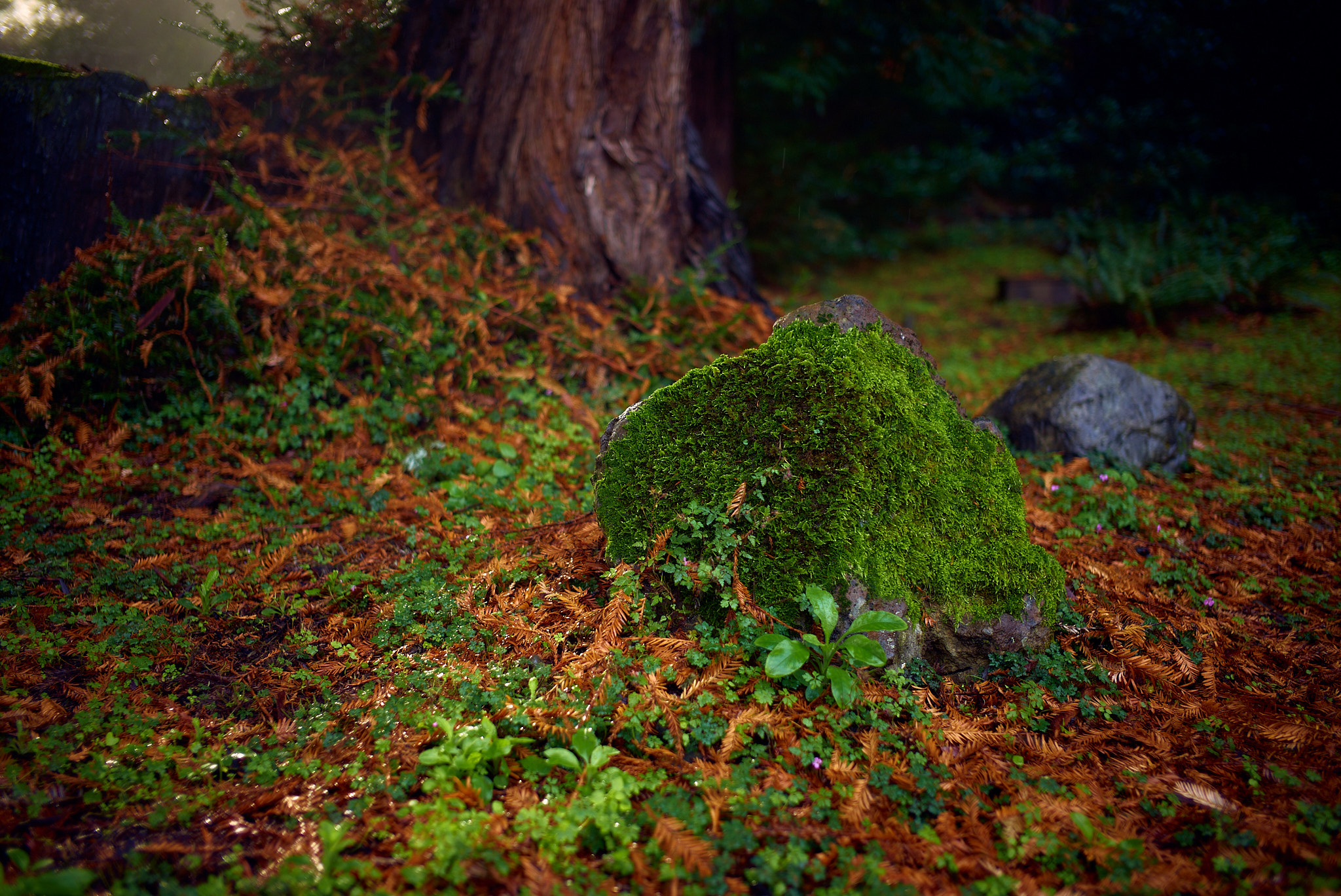
I was doing some digital organization today, including importing photos from my M240, which I apparently neglected to do over the holidays. In addition to the usual Thanksgiving and Christmas photos I found a handful of landscapes I'd made as I was getting read to drive home from my parents' house.
They live up in the mountains, in the middle of a redwood forrest, and often the mornings are foggy and when the sun cuts through the trees at just the right angle its truly magical. The trees glow as the light wraps around the trunks and filters through the branches, everything cool and damp and quiet.
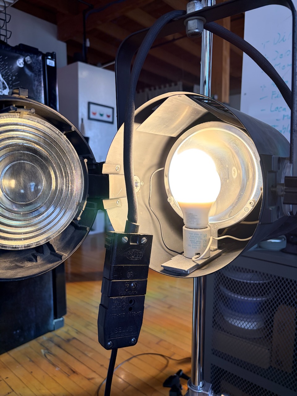
A few weeks ago I visited Urban Ore with some friends, one of whom, a fellow digital tech, pointed out some old-ish theatre fresnel spot lights. They were only $20 so we each picked one up with the intent on retrofitting them to use standard light bulbs. Somewhat surprisingly the light still had a fully functioning lamp, drawing 500W and demonstrating why they're called "hot lights".
The power for the light is provided by a special plug used for lighting called a Bates plug, or formally a Stage Pin Connector, which is basically a chunky, but flat, plug and socket. I wanted my retrofit to be as minimal as possible, so I decided to keep the plug and swung by my local grip shop to get a matching receptacle to splice onto a standard power cable. With the power sorted it was time to move on to the lamp.
The existing socket used a special bulb, and while there are apparently drop-in LED replacements available they cost as much as the entire light did, and I wanted to be able to automate the light with Home Assistant. A second trip to Urban Ore was in order to rummage through the bins of light sockets. I found a nice ceramic one which had mounting holes I could use to attach it to the focussing slide in the light. Again, I wanted to make as few modifications to the original light as possible, so the question of how to actually wire the new socket up remained.
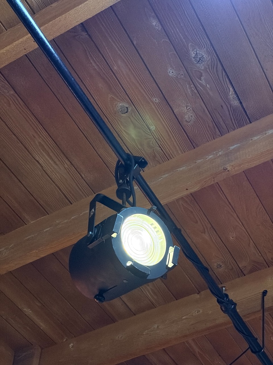
The original wiring was fairly specific to the original socket. I could have just cut the terminals off on each side and crimped them together, but instead I designed a little terminal block which could be mounted on a convenient hole in the back of the housing. It was just a matter of 3D printing it, and a couple of attempts at screwing everything together, and I had a new task light!
I wanted the light to be as bright as possible, any LED was going to be much dimmer than the original 500W lamp, so I tested a bunch of bulbs I had in my collection. The geometry of the fresnel and reflector made the bulb selection and interesting challenge. The brightest bulb I had, at 1500 lumens, was indeed bright, but was too tall, resulting in poor overall performance. I eventually settled on an 840 lumen bulb that placed the actual light emitting portion at the correct height. Interestingly both bulbs gave a roughly equivalent output through the fresnel when measured with a light meter.
I eventually mounted the light to some pipes in the ceiling of my loft, pointed at a shelf to highlight my camera collection. Hanging from the rafters is where this light was meant to be used after all.
Recently a photographer asked me whether there was a better way to build very large TIFFs, a grid of tens of thousands of smaller images, in gigapixel range. My first thought was "sure", thinking I could use some CoreGraphics to put everything together without the overhead of displaying the images. However I quickly found that that perceived lack of overhead was not trivial, and attempting to render small (by comparison) images pushed would simply fail.
I spent a lot of time thinking it over, wondering if there was another angle to tackle the problem from. I wanted to turn this from an imaging problem to a data problem. Could I ignore the pixels and focus only on the bytes? Eventually I turned to the actual TIFF spec to learn how TIFFs are actually put together, and they are, in fact, quite elegant, composed of smaller sections of image data which are combined into the whole.
Usually those sections are made of up strips, a number of rows of the image, but that's not the only option: you can also use tiles. Quoting from Section 15 on tiled images:
However high-resolution images can be accessed more efficiently—and compression tends to work better—if the image is broken into roughly square tiles instead of horizontally-wide but vertically-narrow strips.
Building high-resolution files out of a grid of smaller components? Exactly the problem I was trying to solve.
Building a TIFF Builder
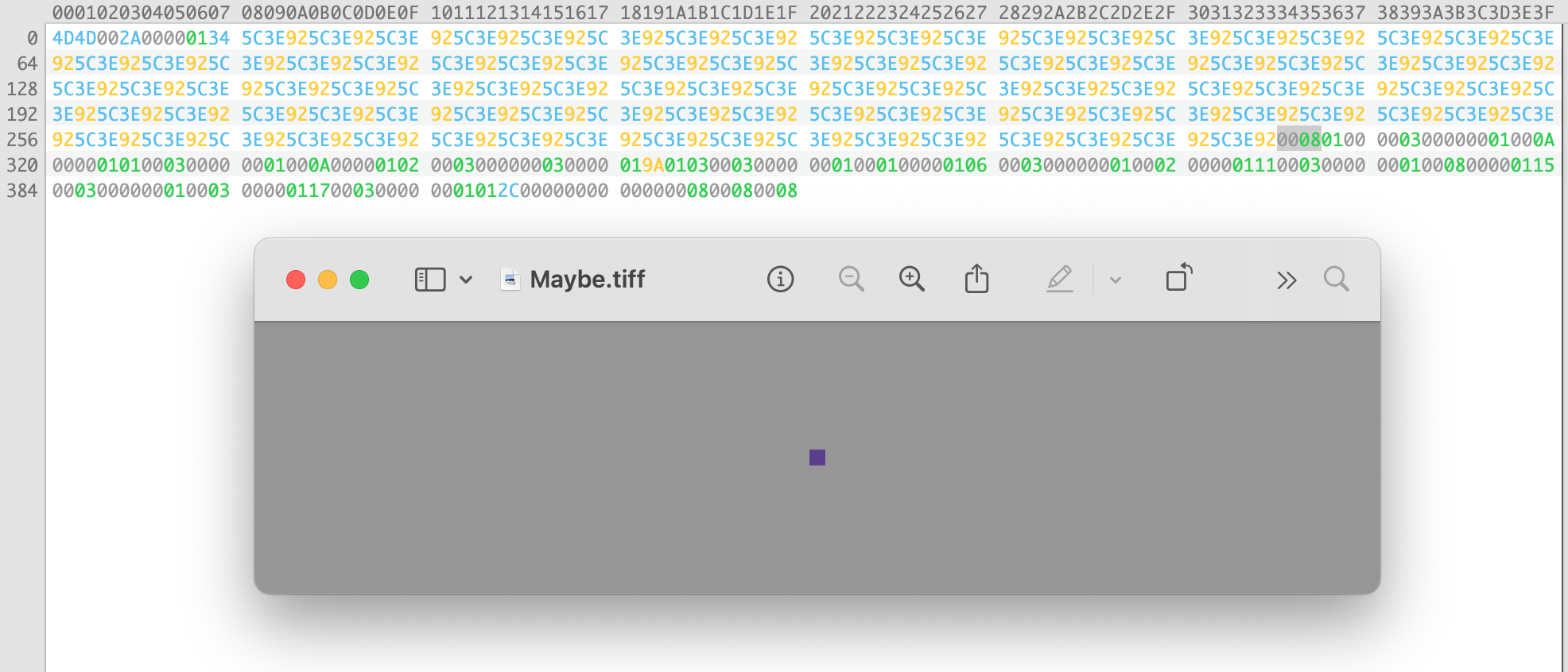
Naturally, to start building my very own TIFF I had to build a TIFF builder. The first thing a TIFF needs is a Image File Directory which describes an image. It contains entries for the size of the final image, compression (we'll get back to that), metadata, and where to final the pixel data in the file.
The very first TIFF I made that was readable was simply a small purple square. All of the values were specified directly in hex, the offsets manually calculated, with the most minimal scaffolding around to make an array of bytes.
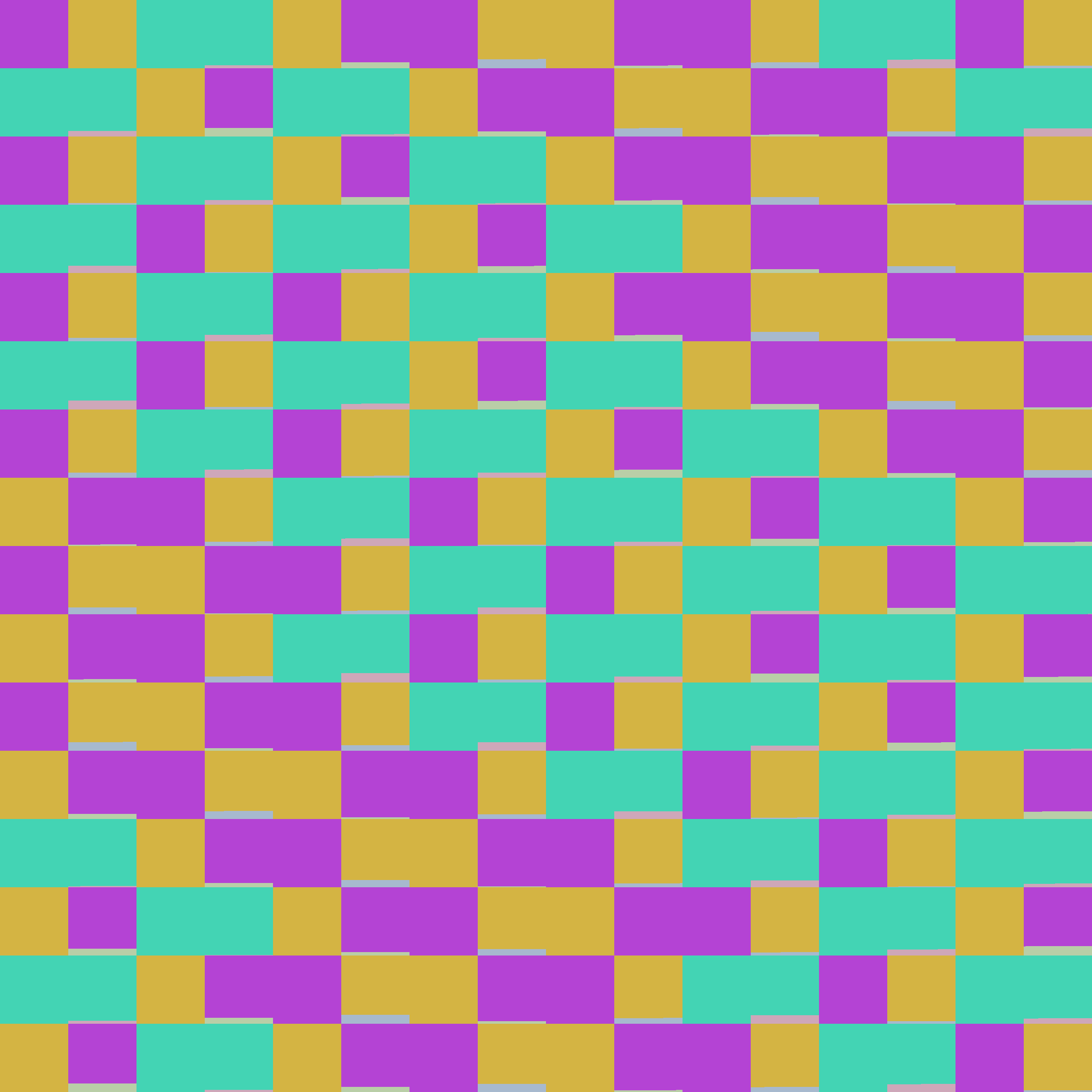
After that I put a few more tags together and built a TIFF made of four tiles in my brand colors. With the basics in place I started writing more of the library, adding enums for tag types, and even added a new Result Builder to an existing library of mine for easily assembling ranges of bytes.
That's when I tried pushing the limits of how many tiles of random colors I could make. Offsets in TIFFs are stored in unsigned 32-bit integers, giving you an address space roughly of roughly four million bytes, which happens to be not that many bytes because I overflowed the UInt32 on the first test. I'd been using raw pixel data: one byte per channel. Remember how I mentioned we'd get back to compression?
Clever Algorithms
As the old saying goes "Hell is implementing clever algorithms." My first try at compression was to implement PackBits, it's relatively simple once you wrap your head around how it works, and I thought it would be perfect for my single-color tiles. What could possibly be more compressible than that?
PackBits made my tiles larger.
The algorithm is, to the specs credit, recommended for bi-lvel images, that is black and white. In this case it's a great way to compress data, just count the number of black or white bytes until you get to a different one. For my images each pixel is repeated, but the bytes never are. Oops, time to try another compression scheme.
LZW compression is the next simplest, which is to say it's not simple. It is, however, exceedingly clever. In broad strokes it encodes runs of bytes in a lookup table created on the fly, though I still don't understand how that table is recreated when decompressing, but that's not my problem. I managed to write a working1 implementation based on the pseudo-code example in the TIFF spec, and was able to encode readable TIFFs, relatively quickly. The issue then was what was being read.
My test images are simply squares of single random colors. See if you can spot the problem, it's subtle.
I was baffled as to why the compression worked until it just stopped. I shuffled the code around, looked at the sample, rewrote the code. Rinse and repeat. After a while I began to notice a pattern: small enough images had all their pixels, but larger images didn't, and interestingly no matter the size of the tiles they cut off after the same number of pixels2.
That's when I began to suspect the code size. LZW uses variable-length code words, starting at 9-bits, so as not to use too many bits in the final data. My implementation was throwing away data when it switched to 10-bit words.
After more refactoring I eventually found the very simple answer: I wasn't adding new entries to the table at the correct offset. A single addition operation and everything worked.
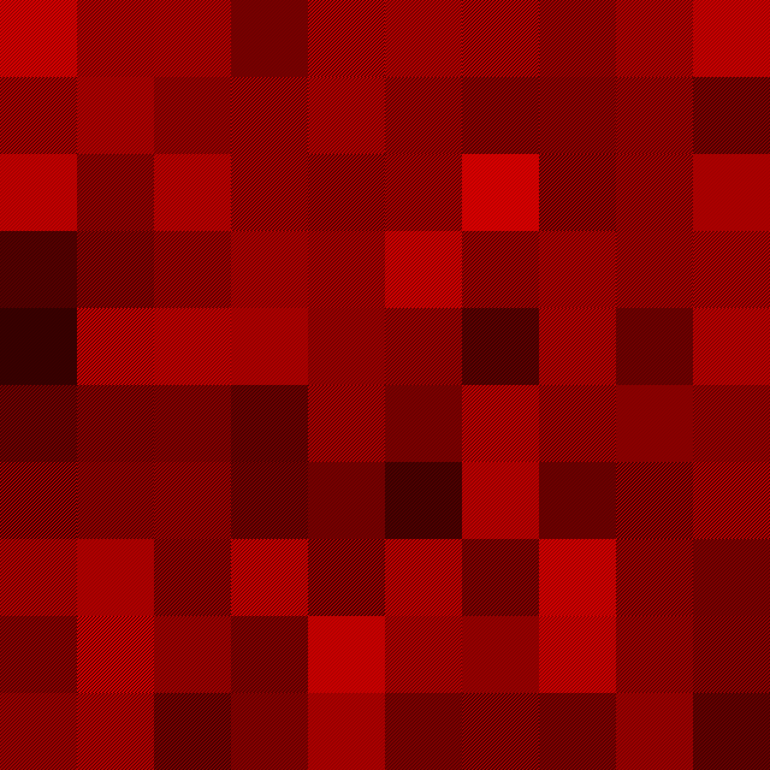
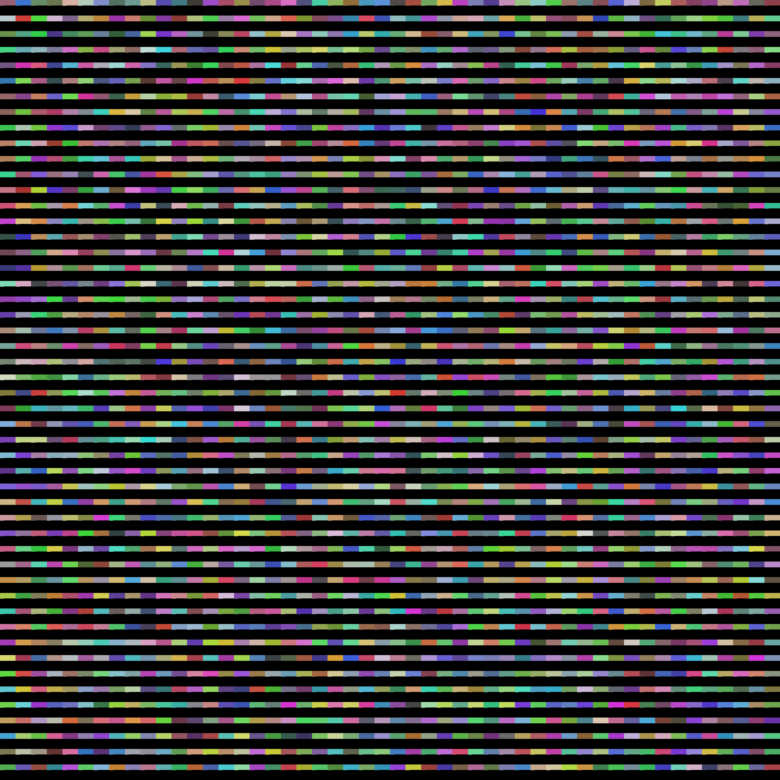
Glitches
In the process of generating TIFFs most of the failures weren't readable, but in the cases where the tags were correct and the pixels valid-ish they would open, and like the example above, be weird. I collected some of my favorites into a gallery, but here are a few examples.
The Library
I've been polishing off the library I wrote to write TIFFs. It's primarily going to be a data-driven way to build TIFFs, bring your own pre-sliced pixel data, with a focus on being as low overhead as possible. Once compression was in-place I was able to build gigapixel test images with 10-15 MBs of RAM usage and with proper multi-threading it can use as many cores as you can give at it.
I am trying to give it the best ergonomics I can, lots of strongly typed inits for fields, and hopefully as little manual offset management as possible. I'll publish it once it's in a place where I think other people can use it, even if I'm the only one who ever does. It's been fun exploring an entirely new domain and I have a feeling it's going to be a useful tool to have.
In March I released a new app, Capturebot 2, and over the last few months I've been fixing bugs and adding a bevy of new features. Today I'm releasing the second update of the year which includes a brand new preset system and several helpful onboarding features.
User Presets & Session Defaults
Capturebot shipped with a handful of built-in presets for capture & output patterns, which were great as building blocks, but didn't fit every workflow. All of that changes with the addition of User Presets which allow you to save as many capture & output patterns as you'd like for easy reuse.
Presets can be created and applied directly from the Session Settings by right-clicking on the pattern name, where you'll find your own presets and the system presets. Perfect for saving your work after you've got the settings for your session just right. Additionally they can be managed from Preferences in the new Presets tab. There you can add, remove, edit, and rename your capture & output presets.
With the addition of presets you can also customize the default document settings from Preferences. You can choose the test folder name, capture pattern, output pattern, and whether to index metadata automatically. New documents will automatically use these options to save some setup time at the beginning of the shoot.
UI Improvements
The interface has also received a handful of small, but useful updates to help you keep track of everything. The most important is the addition of file & shot counts. Available from the View menu enabling "File Count Badges" will show the number of files for each shot, giving you a quick overview of what's been shot and what hasn't. Additionally the number of shots in the shotlist has been added to the inspector.
In an effort to make Capturebot easier to get started with there are several refinements that will be helpful for new users. There are now toolbar items for indexing your capture and output folders and the + button in the sidebar now presents a menu with options to add a new shot or import a shotlist. New filter options are also available in the accessory bar.
Guided Import has also been improved to make it faster and easier to use. After importing your shotlist Capturebot will automatically index the capture folder, showing the files in your session immediately without any additional steps.
Miscellaneous Additions and Fixes
A major under-the-hood change is improved support for external drives, specifically backups to external drives. When opening a document from a backup the capture and output folders correctly point to the external drive, rather than the original folders.
Several buttons and menu items are no longer disabled when they shouldn't be and sidebar buttons have larger hit areas, making them easier to click.
The panel for choosing capture & output folders now defaults to the folder the document is in making session setup even easier. Dragging folders to the capture & output file pickers works correctly and a bug where they wouldn't be saved has been fixed.
Wrapping Up
I'm really happy with the last couple updates to Capturebot, the new features will make the app easier to understand for new users and will help more advanced users work even faster. Capturebot has proven to be invaluable for me on set and I hope it can prove to be just as useful for your own shoots.
Capturebot is available for download1 and purchase from the project page. More details about all of the features can be found on the Knowledge Base.
If you've been using the beta be sure to turn off beta releases in the Update Preferences to download the release version.↩
Last week I travelled to Greece for the first time, in part of join Capture One and work with their engineers1, but also to explore Athens. The entire trip was fantastic, I saw lots of sight, met plenty of people, and took even more photos. I split photos from the trip into two galleries, the first for more general travel photos and the second for the The Acropolis specifically.
The whole experience was amazing, and I can't wait to go back2 because I'm sure there's more to see. I'm particularly pleased with my photos from the Acropolis. Through a lot of patience and careful framing I was able to avoid capturing the hoards of tourists taking selfies. The midday sun helped render the ancient stone in sharp relief and the sky sometimes helps lend an otherworldly quality to the buildings.
I really like the idea of interacting with computers in ways other than the keyboard and mouse, especially in ways that can control applications without concern for focus. That's a big part of why I like the Stream Deck and built a plugin for Capture One. Through happenstance I needed to build an input device to emulate a barcode scanner, so I rummaged around the parts bin and grabbed a Raspberry Pi Pico and a clicky arcade button and tossed a sample project together. Of course it didn't stop there.
Once I had the button put together I wondered what else I could do with it.
The Hardware
The sensible thing to do would have been to grab an off-the-shelf RP2040 board and call it a day, however I've been designing a custom PCB for my GPI Controller and, if you squint, the who projects are basically the same. All of the support electronics for the RP2040 (flash, crystal, decoupling capacitors, etc.) could be shared, it's just what happens to the GPIO lines. A quick copy and paste later and I was on my way to a fresh new PCB.
While the current prototype only had a single button I wanted to design the board to be a little more modular so I could use the design for more projects in the future. I landed on adding headers for four button/LED pairs, each on a JST connector for ease of use. This also opened the door for users designing their own enclosures and adding more buttons if they wanted.
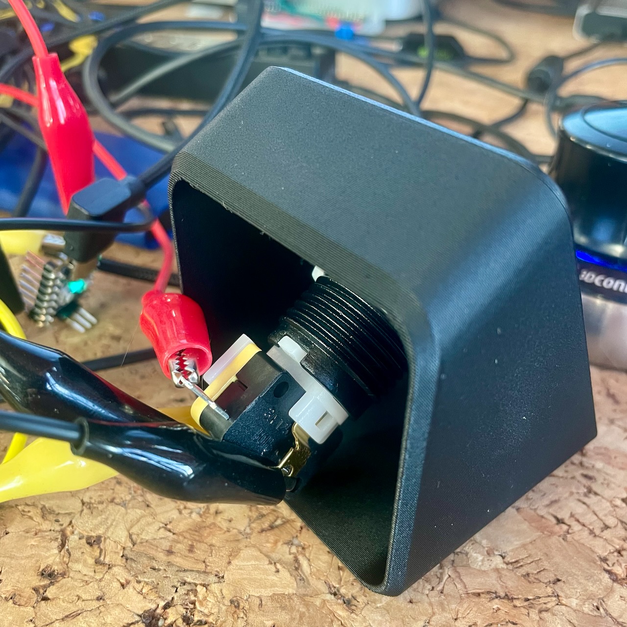
Surprisingly enough the enclosure turned out to be more work than the PCB. The buttons I chose are long once the microswitch is installed and I wanted to keep the overall size down. This introduced a lot of constraints around the overall dimensions, and critically the maximum angle of the front face in order for the button the clear the PCB.
The initial versions technically fit everything inside, but at the expense of being impossible to assemble: there was no way to insert the LED and microswitch without disabling clipping in the physics engine of reality. Unhappy with the 3D printed enclosure I looked into designing a sheet metal enclosure which would be laser cut and bent into shape.
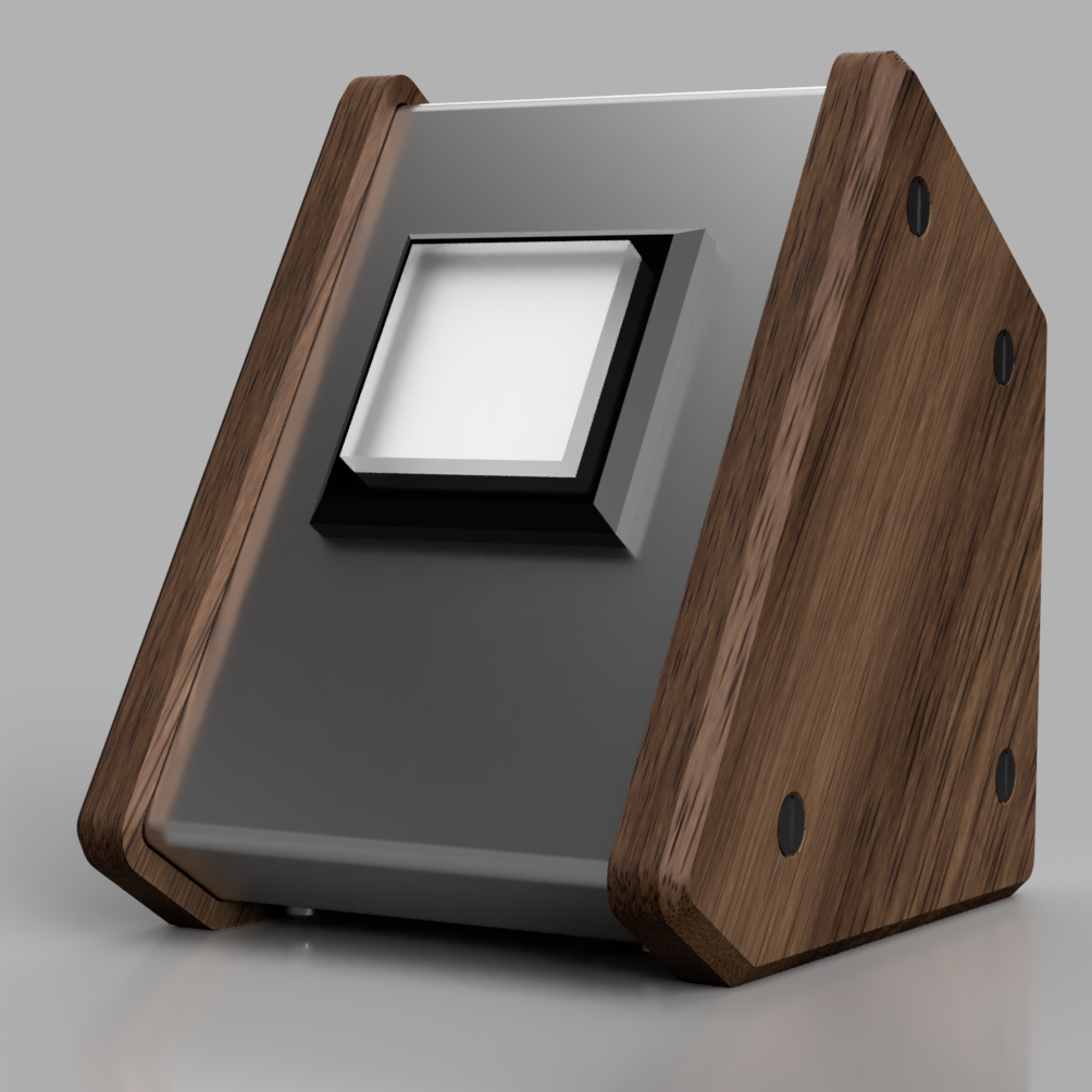
I still really like how it looks but there are limitations to what can be easily (and affordably) manufactured. Initially I designed a full wrap-around part, but metal breaks can't form parts into enclosed shapes. Next I broke the bottom part out, but in order to use an appropriate thickness of material the bends would interfere with the tapped holes. Then there were the tapped holes, lots of them which pushed the price beyond what was reasonable.
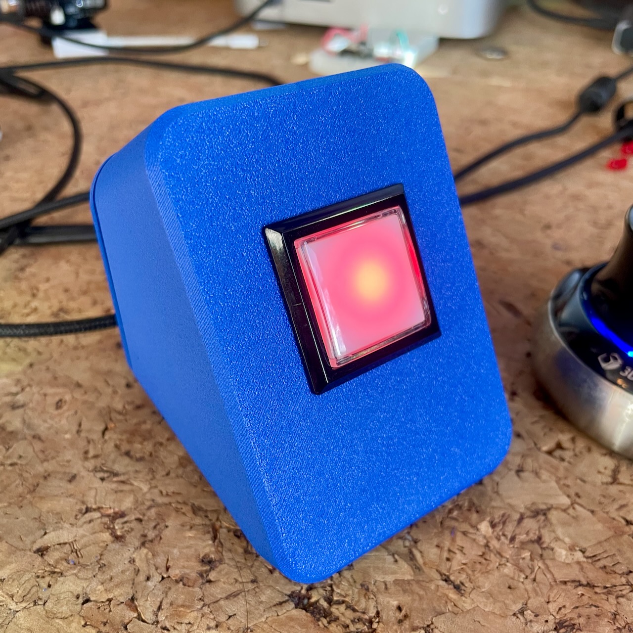
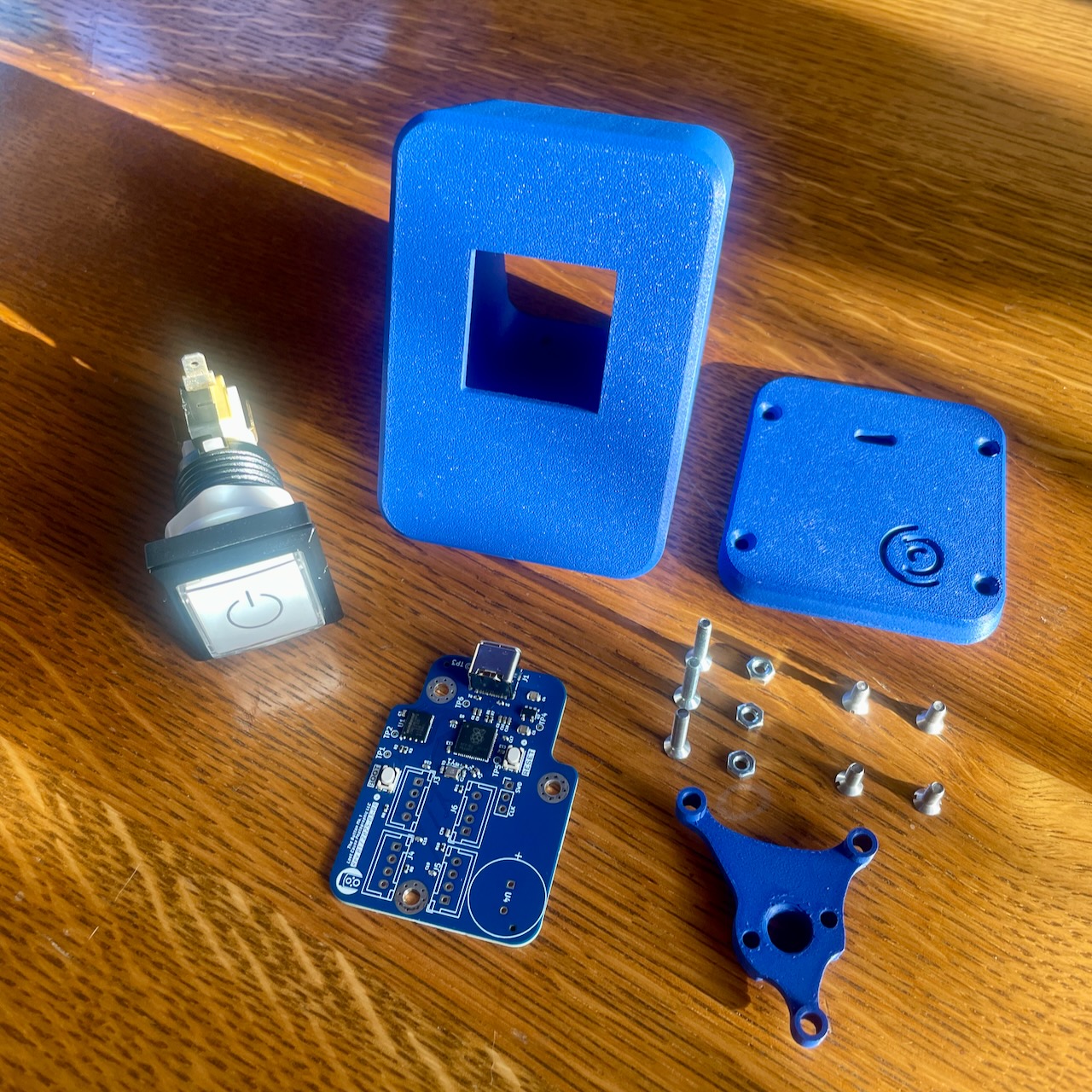
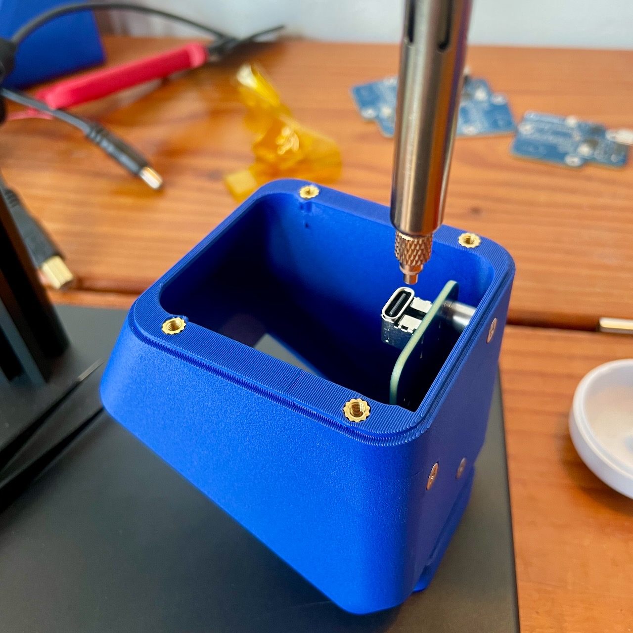
Eventually I went back to the "unibody" 3D printed enclosure, iterating on the design to make the smallest practical enclosure. At the end of the day I settled on a three-part design: the main enclosure, a back plate, and a special keyed spacer that includes ARRI anti-twist pins. It's only 66mm x 86mm x 85mm with the face at a 60° angle and there's a slight taper along the sides.
The main enclosure prints face-down without supports and gets four M3 threaded inserts to hold the back plate in place. The spacer clicks into place from the inside and is doubly secured once clamped between the enclosure and PCB. Finally the button is threaded in, sitting just above the USB-C port.
The Embedded Software
While developing the GPI Controller and GB Link I build a common USB data protocol to communicate with my embedded projects. The GPI Controller was programmed in C, but for the GB Link I used Swift for the embedded side as well. Embedded Swift is still fairly new so there are some hurdles to clear.
One big improvement with the button codebase over the previous iteration was putting the shared models into a separate library inside the Swift package. This way the files could be imported as a library by the macOS client code and referenced by the makefile to build the embedded version. While this is better, especially using globs to find the files instead of manually referencing each one I'd still like to figure out how to move more of the build step into the Swift environment.
A key place this comes in is that there are a number of shared models, like the data header, which need to be copied from the USB protocol library into the embedded codebase because the library can't be imported. If the embedded codebase could be built with swift-build it could, theoretically, import libraries so long as they've been annotated with the appropriate availability statements. This would mean both the embedded binary and client library could fully share common models which would be kept in sync as the API changes.
The Client App
The companion app for the GPI Controller, ControlRoom was the natural home for the new hardware project. Adding initial support was simple because most of the infrastructure had already been built for the previous projects. The major new task was adding configurable actions. Easy enough, right?
As it turns out, not entirely. The basic actions aren't difficult, but ensuring they work outside of being instantiated inside the SwiftUI view hierarchy proved more difficult. I ended up having to partially rewrite by configuration storage system so it wasn't tightly coupled to the hardware types, revise how I handled USB connection events to when connecting a button the actions could be wired up, and finally moved everything into a separate agent binary which can be run by launchd independently from the main app.
The end result is quite nice though, and ends up working a little like the GPI Controller Stream Deck plugin. Each binary uses File Presenters to coordinate reading and writing the configuration files. In practice this means when the user changes the action or settings the changed is picked up by the agent and the button is reconfigured, even opening the JSON in another application will similarly update the UI.
The configuration UI, while a little basic, is particularly fun because the large squares on the left show the whether the button is physically pressed or not and whether the LED is on. Both states even combine into a pressed and illuminated visual.
Bonus: AppleScript
I wanted the buttons to be scriptable, both that they could trigger AppleScripts and that they could be configured via AppleScript. Using AppleScriptBridge I was able to easily implement custom handlers in a user's script so they could receive keyDown and keyUp events with parameters for the device and the button number that was pressed.
Inside those handlers the user can perform whatever actions are needed, but they can also control the LED. It's kind of a small thing, but also very cool that you can use AppleScript to control external hardware.
Wrapping Up
Overall I'm really proud of the outcome. It combines nearly all of my hobbies into one project, and with all of the tangents (like sheet metal and embedded Swift) I ended up learning a lot about things I'd only dabbled in before. I'm not entirely sure what the plans are for the project, I'll probably sell it as a finished product as well as a kit.
I want to add more actions, although the scripting support can augment some of that. I can also see using this as a good excuse to test out ExtensionKit to allow for 3rd party actions, but maybe I'm getting ahead of myself.
For the past few months I've been working on a brand new app to help digital techs on set. Capturebot 2 is designed to help digital techs manage their sessions by building a shotlist and tracking files ensuring that everything is named and processed correctly.
The History
The premise behind Capturebot is something I, and others like Brian von Glahn, have been messing with for a while. I'd built scripts and small command line tools to traverse the file system matching RAW file and output file together, but they were always a little clunky. I'd get something working on my computer, send it to a friend to test, only to find they set their sessions up differently, so the tool didn't work. Each time I shelved the idea because the scope was too large.
The work on Capturebot really began when I got the dreaded call after a shoot asking about some files. I checked my backup only to discover that, indeed, at the end of a week-long shoot a couple shots were missing output. I used that session as a standard test when building Capturebot.
What Capturebot Does
Capturebot, at its core, searches for RAW files and output files in order to find errors that I'm sure every digital tech has encountered at some point. It's designed to be flexible enough for any workflow and fast enough that Capturebot can be used throughout a shoot to help catch possible issues early.
The entire system is built on a powerful token-based file matching system which scans your session for RAW files and assigns them to shots. It can also be used to automatically build your shotlist as you go, for those shoots where you don't have a pre-built shotlist. Any files that are in the wrong folder or have naming errors will be flagged foe easy review.
Capturebot can also read metadata from your RAW files. This is particularly useful in the cases where an art director needs to make selects on set as you can easily see what shots have tagged or rated images, and how many of each. The metadata can be read from Capture One settings files, XMP sidecars, and even directly from inside an EIP.
By leveraging the same token engine Capturebot can quickly identify any RAW files that are missing output. For each process recipe you define a corresponding output pattern which tells Capturebot exactly where to expect to find the file. Any missing files are shown in a list so you don't have to hunt for them.
Finally Capturebot can generate reports in a variety of formats for your session. The reports can be shared with the photographer, client, producer, or anyone else as a way to help verify that everything is as it should be. You can make reports for the whole session or for individual shots as needed.
Where to Get It
Capturebot has been in an extended beta by some of the top techs in the industry and is now available for download. There is a fully-featured two week trial available and it can be purchased for $99, which includes a full year of updates. Ongoing updates are available with a $49/year subscription.
The updates subscription is, of course, optional, and importantly you will always keep what you've paid for.
I have big plans for Capturebot with a long list of features to add like shot status tracking, metadata import and writing, customizable reports, rule-based output matching, additional summaries, and more.
Give Capturebot a try, read the documentation, and let me know how it fits into your workflow.
The first app update of the year goes to First Contact with a minor update bringing enhanced menu bar functionality, some bug fixes, and support for images with an alpha channel.
Main Features
First Contact now has a brand new Page menu, which has a suite of commands for changing the page layout. The header, footer, and image labels can be toggled from the menu bar, or with keyboard shortcuts, as can the grid's rows and columns.
The biggest addition is the Match Fonts commands, which will sync the font family, size, and color between the header, footer, and image labels. This makes updating the font selection in a layout faster as each group no longer needs to be set manually.
Extras
Images with transparency, like screenshots, are now rendered correctly, with the page color showing through the image
The metric page presets have been recalculated to provide accurate sizing in millimeters and the A4 page defaults to landscape like the other page sizes
All images can be removed from the Edit menu, and when removing the last image the PDF size estimate correctly reflects that fact
You can also remove an image by right-clicking on it in the PDF preview
Files and folders can be dropped into the PDF preview area, not just the sidebar
The app now uses a custom accent color, matching the rocket in the icon
The update is available now via the in-app updater or by downloading directly. As always there is a two week trial available.